Using Mol*
Mol* is an excellent tool for viewing biomolecular structures, comprising three fundamental modules: Structure Viewer, Sequence Viewer, and Structure Objects Viewer.
Mastering the following basic concepts will make using Mol* much easier:
Component
A component is a subset of the protein structure. In Mol*, some components are automatically constructed when opening a structure file, such as "Polymer" (all polymers like DNA, RNA, proteins), "Ligand" (all small molecule ligands), "Water" (all water molecules), etc. Some components can be created using the "Interface Display" feature, such as "Chain A" (all atoms in chain A), "Interface with BC" (amino acids in chain A interfacing with BC), etc. You can also create your own components. Components can be nested.
Representation
Representation is the visualization style of structures/components. Common representations include "Cartoon", "Ball & Stick", "Spacefill", etc.
Selection
In Mol*, a selection refers to the atoms you have selected in the Structure Viewer. Notably, selections must be made in Selection Mode. Clicking on atoms in the Structure Viewer in default mode will trigger a “Focus” operation.
Structure Objects
Structure objects are 3D objects displayed in the Structure Viewer. They can be accessed via the Structure Objects component, located at the bottom-left of the Project Editor. The Objects component contains a list of files that are currently open (i.e., has a light blue background in the Files & Jobs panel).
Each file is displayed in a tree-like structure, with the following hierarchy:
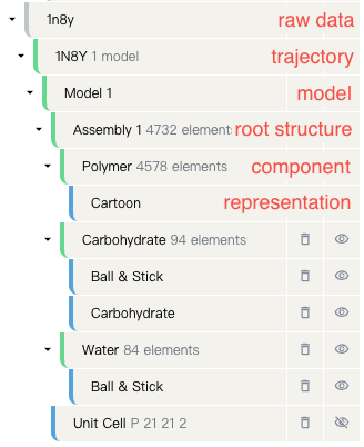
Raw Data
This refers to the original data of the file, typically in PDB or mmCIF format. If the file is imported from the cloud, this information might not be displayed.
Trajectory
Similar to a video, a trajectory is composed of a series of models (snapshots), representing the structural changes over time or a collection of related structures.
Model
A snapshot within the trajectory, similar to a 3D image. You can switch models by clicking "Update Model" under the trajectory entry and selecting the desired model. Most protein structure files contain only one model as they store static structures.
Structure
A collection of atoms. Structures can be constructed in various ways from a model. Many protein structure files define several assemblies, with the first assembly displayed by default. If no assemblies are defined, all atoms in the model are included in the root structure.
Ways to construct the root structure from a model
Given a properly annotated mmCIF/PDB file, you can construct the root structure from a model via multiple ways.
- Model: Incorporates all atoms from the model into the root structure.
- Assembly: Constructs the structure based on the assemblies defined in the file.
- Symmetry: Applies user-defined symmetry operations, such as translation, rotation, or mirroring, on the assymetric units, to create the structure.
- Symmetry Mates: Creates a structure by finding symmetry mates within a certain radius. Symmetry mates are images of the asymmetric unit created by symmetry operations.
- Symmetry Assembly: Uses defined symmetry operators and asymmetric units to construct a custom biological assembly.
- Auto (default): Creates a "model" structure if there are no available assemblies. Otherwise, defaults to the first assembly.
You can change how the root structure is constructed by clicking on it -> "Update Structure" and selecting the desired structure construction method.
Component
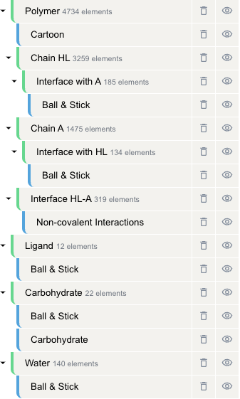
A subset of the structure containing one or more atoms, such as "Polymer" (e.g. DNA, RNA, proteins), "Chain A" (all atoms in chain A), etc. Components can be nested - you can nest a component within another component. You may also expand, shrink, delete, rename, or save a component as new files (more about that here). By defaults, the root structure is split into components in this way.
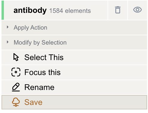
Actions on Components
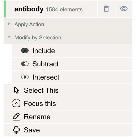
Clicking on a green component entry in the Structure Objects Viewer will open a menu where you can perform the following actions:
- Show/Hide a component using the "
 /
/ " button.
 - Delete a component with the "
 " button. This will remove the component grouping, but the structure itself will remain unchanged.
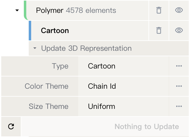
 - Update representation by selecting "Apply Action" -> "Update 3D Representation" and choosing the desired representation type, color theme, and size theme.
- Modify selection based on the current selection by selecting "Apply Action" -> "Modify by Selection" and choosing one of the following operations:
 Include: The new component will include both the current and the selected component.
 Subtract: The new component will exclude parts that overlap with the selected component.
 Intersect: The new component will consist of only the overlapping parts of the current and selected components.
 Select This: Set the current component as the selection.
 Focus This: Focus on the current component.
 Rename: Rename the current component by entering a new name in the text box.
 Save: Save the current component as a new file.
Representation
The visualization style of structures/components. It defines how structures are displayed in the 3D canvas of the Structure Viewer. Details on all supported representations can be found here.
Supported Representation Types
The following representation types are supported by Mol: - Cartoon: Displays ribbons, planks, tubes smoothly following the trace atoms of polymers. - Backbone: Displays polymer backbone with cylinders and spheres. - Ball & Stick: Displays atoms as spheres and bonds as cylinders. - Carbohydrate: Displays carbohydrates as symbols (3D SNFG). - Ellipsoid: Displays anisotropic displacement ellipsoids of atomic elements plus bonds as cylinders. - Gaussian Surface: Displays a gaussian molecular surface. - Gaussian Volume: Displays a gaussian molecular density using direct volume rendering. - Labels: Displays labels for atoms, residues, and chains. - Lines: Displays bonds as lines and atoms as points or croses. - Molecular Surface: Displays a molecular surface. - Orientation: Displays orientation ellipsoids for polymer chains. - Point: Displays elements (atoms, coarse spheres) as points. - Putty: Displays a tube smoothly following the trace atoms of polymers. - Spacefill: Displays atomic/coarse elements as spheres. - Non-covalent Interactions: Displays non-covalent interactions as dashed cylinders. - Validation Clashes: Displays clashes between atoms as disks. Data from wwPDB Validation Report, obtained via RCSB PDB. - Membrane Orientation*: Membrane Orientation calculated with ANVIL algorithm.
Besides the representation type, there are two key parameters that determine how the structure is displayed: color theme which determines the coloring, and size theme which determines the size of the representation.
Representation Presets
Representation presets are pre-defined structure display styles that can create multiple components from a root structure and apply appropriate display styles to each component. Here we will introduce the default behavior of Mol* when opening a structure file, and also touch on some details of representation presets.
The decision for representation happens in two major steps:
-
Size Determination: The size of the structure is classified into five categories: Small, Medium, Large, Huge, and Gigantic.
-
A structure with a residue count less than 10/5000/30000 is considered "Small", "Medium" and "Large", respectively.
-
If a structure has a > 30000 residue count, it is categorized as "Huge" if it has a high symmetry unit count; otherwise, it's "Gigantic".
-
-
Representation Selection: Based on the size determined, an appropriate representation is chosen. The logic is as follows:
- Small: Use the AtomicDetail display with carbohydrate symbols. When there are many atoms, use line representation for atoms and point representation for coarse elements. When there are few atoms, use spacefill representation for both atoms and coarse elements.
-
Medium: If the residue : polymer gap ratio is greater than 3, use the PolymerAndLigand preset, creating the following components:
- Polymer: Display the polymer chains (like proteins, DNA, RNA) with Cartoon representations of their secondary structures.
- Ligand: Display the ligands (small molecules) as Ball & Stick representations.
- Non-standard: Display the non-standard amino acids as Ball & Stick representations.
- Carbohydrate: Display the carbohydrates as ball & stick and 3D-SNFG representations (named "Carbohydrate").
- Water: Display the water molecules as Ball & Stick or Line representations (when there are many water molecules).
- Ion: Display the ions as Ball & Stick representations.
- Lipid: Display the lipids as Ball & Stick or Line representations (when there are many lipids).
- Coarse: Display the coarse elements as Spacefill representations (when there are many coarse elements).
Note that if the corresponding component type does not exist in the structure, it will not be created. If the residue : polymer gap ratio is less than 3, display in the same way as "Small".
-
Large: Use a PolymerCartoon preset where only a Polyer component is created with a Cartoon representation.
- Huge/Gigantic: Use the CoarseSurface preset, which creates a Polymer and a Lipid component with gaussian surface representations.
The automation here helps provide an optimal view of the molecular structure based on its size and complexity, essentially balancing detail and performance.
Structure Viewer
The Structure Viewer is the main component of Mol*. It displays the 3D structure of the molecule(s) in the PDB file(s) that are currently open. It is located in the center of the screen.
Mouse controls
- Rotate: click the left mouse button and move. Alternatively, use the Shift button + left mouse button and drag to rotate the canvas.
- Translate: click the right mouse button and move. Alternatively, use the Control button + the left mouse button and move. On a touchscreen device, use a two-finger drag.
- Zoom: use the mouse wheel. On a touchpad, use a two-finger drag. On a touchscreen device, pinch two fingers.
- Center and zoom: use the right mouse button to click onto the part of the structure you wish to focus on.
- Clip: use the Shift button + the mouse wheel to change the clipping planes. On a touchpad, use the Shift button + a two-finger drag.
- Highlight: hovering over any part of the 3D structure displayed in the Structure Viewer, without clicking on it, will highlight it (by coloring it in magenta) according to the current Picking Level. Additionally, in the bottom right of the Structure Viewer, information about the PDB ID, model number, instance, chain ID, residue number, and chain name is listed for the highlighted part of the structure.
- Focus: In default mode (i.e. non-selection mode), click on a 3D object to focus on it. The focused object and its surroundings will be displayed in a ball & stick representation. All local non-covalent interactions will be shown. To hide the surroundings, click on the target residue again. To un-focus, click on any point in the Structure Viewer that has no atom.
Toggle Menu
This menu provides users quick access to some commonly used operations for the Structure Viewer. It is located towards the right side of the Structure Viewer and has the following functions.
| Function | Description | Icon |
|---|---|---|
| Reset Camera | Centers and resets the view of the structure on the Structure Viewer | |
| Screenshot/State Snapshot | Takes an image of the structure as shown and gives options for resolution and download | |
| Expanded Viewport | Expands Structure Viewer and Controls Panel to the full browser screen | |
| Settings/Control Info | Provides settings for viewing of Structure Viewer, as well as information about moving in 3D and mouse controls | |
| Measurements | Displays and creates various measurements | |
| Superposition | Rotates and translates molecular structures to make them match other structures. | |
| Interaction Visualization | Displays intra-chain or inter-chain non-covalent interactions | |
| Selection Mode | Switches between Default Mode and Selection Mode |
Selection mode
You can enter the Selection Mode by clicking on the "![]() " icon in the Toggle Menu.
" icon in the Toggle Menu.
In selection mode, a click on a residue (or any object in 3D) will select it (instead of focus it in the default mode). What exactly will be selected depends on the value of the Picking Level. Selected parts of the structure will appear with a bright green tint both in the Structure Viewer and in the Sequence Viewer. Clicking on any point in the Structure Viewer that has no atom will clear the selection.
When selecting polymers with the Picking Level set to “Residue”, holding the Shift key while clicking will extend the selection along the polymer from the last clicked residue on. One could also press, drag along the polymer sequence and release in the Sequence Viewer to select multiple residues.
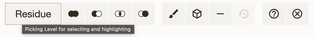
Activating Selection Mode opens a toolbar that appears at the top of the Structure Viewer. The following provides an illustration of the toolbar and a description of each of the buttons:
| Function | Description | Icon |
|---|---|---|
| Picking Level for Selecting and Highlighting | Controls to what level a selection or highlight interaction is applied (i.e., atom, residue, chain, etc.) | |
| Add/Union Selection | The new selection will be the union of the current and the other selection | |
| Remove/Subtract Selection | The new selection will be the current selection with parts that are in the other selection removed | |
| Intersect Selection | The new selection will be the intersection of the current selection and the other selection | |
| Set Selection | The new selection will be the other selection | |
| Apply Theme to Selection | Enables changes of color, transparency and clipping to be applied to the current selection | |
| Create Component of Selection with Representation | Enables components to be created and its representations to be changed independent of other components | |
| Remove/Subtract Selection from All Components | Removes the current selection from being displayed in the Structure Viewer | |
| Undo Modify Selection | Allows certain actions (changes of color, hiding of components, etc.) to be reverted while remaining in the selection mode | |
| Show/Hide Help | Offers a summary of selection operations, representation operations, and mouse controls | |
| Turn Selection Mode Off | Switches from Selection Mode to Default Mode |
Picking Level
The Picking Level controls to what level a selection or highlight interaction is applied. Specifically, a selection/interaction can be extended from a single atom to a residue (default), chain, entity, model, or structure. For example, if you click on an atom on the Structure Viewer and the picking level is set to "chain", you would end up selecting the whole corresponding chain of that atom. If the structure contains symmetry instances and the picking level ends with "instances" (e.g. "chain instances"), the interaction would be extended to include all atom / residue / chain instances of the clicked atom.
In addition, the picking level determines the specificity of a selection in the Sequence Viewer, or the specificity of the focus in Default Mode.
The Picking Level can be changed via a menu in the Selection Mode toolbar located at the top of the Structure Viewer.
Creating a component
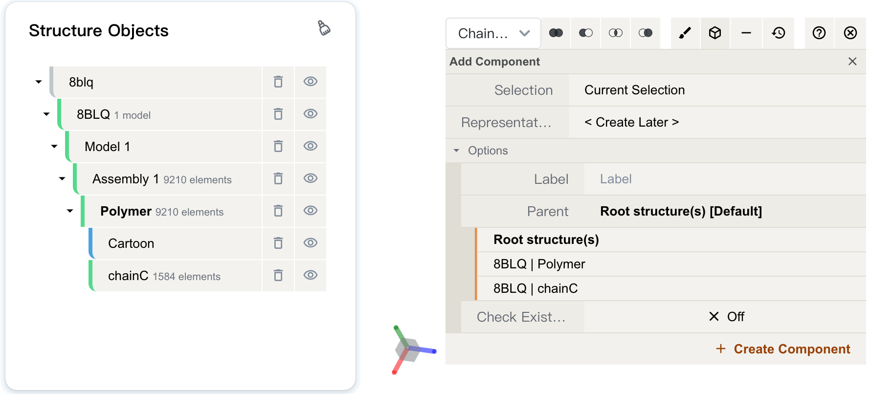
Under selection mode, we can create a new component from selections. Creating components allows the user to make groupings of certain parts of a structure for subsequent manipulation (see Actions on Components). For example, if you want to visualize a protein and its ligand separately, you can create a component of the ligand and hide it. Then you can change the representation of the protein without the ligand being in the way.
You can create a component by clicking on the "![]() " button, located in the Selection Mode toolbar at the top of the Structure Viewer. A menu will appear, where you can fill in the following parameters:
" button, located in the Selection Mode toolbar at the top of the Structure Viewer. A menu will appear, where you can fill in the following parameters:
- Selection: the selection to be used to create the component. Defaults to the current selection. You can also use a new selection that consists of, e.g. a certain amino acid type (by selecting "Amino Acid > Alanine (ALA)", for example), or all surrounding residues of the current selection (by clicking "Manipulate Selection > Surrounding Residues (5Å) of Selection").
- Representation: the representation to be used for the component. Defaults to None.
- Options:
- Label: label of the component. Defaults to "Label".
- Parent: the parent component of the new component. Defaults to "Root Structure(s)". If the selection spans multiple root structures, a new component will be created under each structure's root. You can also select a specific component as the parent component, in which case the new component will be the intersection of the selection and the parent component.
- Check existing: checks if a selection with the specifield elements already exists to avoid creating duplicate components. Defaults to false.
Once you click on "Create Component", the component will be created and displayed in the Structure Objects panel. You can now perform actions on the component.
Example: extract antibody chains from a complex structure and save it
If you would like to extract the antibody chains from an antibody-antigen complex structure and store them to another file, you can follow the steps below:
- Import the complex structure file from cloud or upload it from your local machine. Open the file by clicking the file name in the Files & Jobs panel.
- Open the selection mode by clicking the "" button on the right of the Structure Viewer.
- Change the picking level to "Chain", then click on the chains of the antibody to extract.
- Create a component named "antibody" by clicking the "
 " button on the top of the Structure Viewer.
 -
Save the component to a CIF file in the project by clicking the "antibody" component in the Structure Objects panel and then clicking "Save" in the dropdown menu. Enter the file name to create and click "√".
-
Now there will be a new CIF file in the Files & Jobs panel.
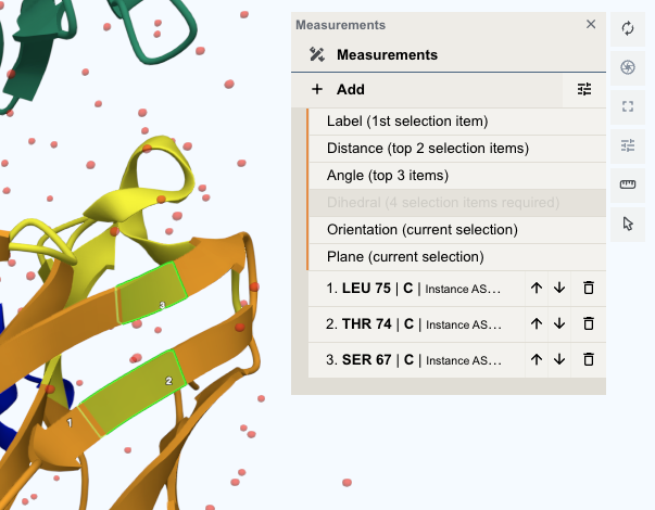
Measurments
Click the "![]() " icon in the Toggle menu to open the measurement menu. Click "+Add" to create a new measurement object based on the current selection. The following measurement types are supported:
" icon in the Toggle menu to open the measurement menu. Click "+Add" to create a new measurement object based on the current selection. The following measurement types are supported:
| Type | Selection Count | Description |
|---|---|---|
| Label | Last 1 | Label of the selection |
| Distance | Last 2 | Distance between two selections |
| Angle | Last 3 | Angle formed by three selections |
| Dihedral | Last 4 | Dihedral angle formed by four selections |
| Orientation | All | Create a parallelepiped that includes the selection lists |
| Plane | All | Create a plane that has the smallest sum of squared distances to the selection |
You can view and edit the current selection list in the measurement menu. By default, the selections are ranked by the time they were added to the selection list, with the first selected selection being ranked at the bottom and the last selected selection being ranked at the top. You can click the "↓" or "↑" button to adjust the order of the selections.
Superposition
The Superposition Panel rotates and translates molecular structures to make them match other structures. Mol* performs superpositions by matching selected chains or atoms. The root-mean-square deviation (RMSD) of the superposed structures will be provided in notification after superposition.
To access the Superposition Panel, click the "![]() " button in the Toggle menu.
" button in the Toggle menu.
Superposing by Chains
In order to superpose structures by chains, two or more selections from separate structures are required. For each PDB entry, selections must be limited to single polymer chains per structure. After making two or more selections, click “Superpose” to superpose the structures in the 3D canvas. While the superposition is per chain, the resulting 3D transformation is always applied to the whole structure. When superposing more than two structures, note that the alignment is done with respect to the first structure.
Superposing by Atoms
In order to superpose structures by atoms, one or more atoms from separate structures must be selected. Select one or more atoms and click “Superpose” to superpose the structures in the 3D canvas. The superposition is done on all given pairs of atoms in the order they appear in the panel. To reorder the atoms, use the up and down arrows in the panel.
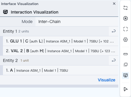
Interaction Visualization
The Interaction Visualization panel displays detailed information of intra-chain or inter-chain non-covalent interactions.
To access this panel, click the "![]() " button in the Toggle menu.
" button in the Toggle menu.
You may choose to visualize intra-chain or inter-chain interactions. For "Intra-Chain" mode, your selected entity (i.e. substructure) must lie within a single chain. For "Inter-Chain" mode, selected entities should come from different chains. Click "![]() " to set the target entity as the current selection.
When you are ready, click "Visualize" to display the interactions.
" to set the target entity as the current selection.
When you are ready, click "Visualize" to display the interactions.
For interaction result display, see Interaction Viewer.
Sequence Viewer
The Sequence Viewer displays the polymer sequences of macromolecules (proteins and nucleic acids) present in the PDB structure(s). In addition, it provides quick access to any small molecular ligands or entities present in the structure(s). It is located at the top of the screen above the structure viewer.
The Sequence Viewer contains several drop-down menus that allow the user to choose which sequnece to display:
- Structure: select which structure to display.
- Mode: select between three display modes: chain, polymers and everything. In the chain mode, each chain is displayed as separately. In the polymers mode, all polymers are displayed together. In the everything mode, all entities are displayed as together.
- Entity (only in chain mode): select which entity to display.
- Chain (only in chain mode): select which chain to display.

On the top-right of the panel, there are three buttons:
 (Copy): Copy sequence/site information to clipboard. Supported operations include:
- Copy structure sequence (as FASTA): Copy the sequence of the current structure as FASTA format.
- Copy chain sequence: Copy the sequence of the current chain (including missing residues).
- Copy selected sequence: Copy the sequence of the current selection.
- Copy selected sites (label): Copy the sites of the current selection, e.g.
A:67-71,B:3. For a CIF file, the chain and residue IDs are extracted from thelabel_asym_idandlabel_seq_idfields of theatom_sitetable, respectively. - Copy selected sites (author): Copy the sites of the current selection, e.g.
H:95-99,H:100B,H:100C. For a CIF file, the chain IDs are extracted from theauth_asym_idfield of theatom_sitetable, while the residue IDs are extracted from theauth_seq_idandpdbx_PDB_ins_codefields.
 (Wrap sequence): Wrap the sequence to fit the width of the panel. If disabled, the sequence will be displayed in a single line. Defaults to true.
-
 (Sequence Annotation): Displays the secondary strcture, CDR region or surface residues of the sequence with wavy or straight underlines. Clicking it will open a sequence annotation configuration window. The supported options are:
- No annotation
- Display secondary structure: Alpha helices in the sequence are wavy-underlined, and beta sheets are straight-underlined.
- Display CDR (complementarity-determining region) region: The corresponding CDR residues will be underlined. Supported CDR definitions include "IMGT", "Chothia", "Kabat" and "North".
- Display surface residues: The surface residues are underlined. Note that the surface is relative to the root structure, not individual chains. Therefore, residues on binding interfaces and buried by their binding partners are not considered surface residues.

Sequence Annotation